Maker V1 and V0

Maker has gone from version V0 to V1 with some improvements/modifications. The latest Maker, Version V1.0 with its added features enhances accuracy and provides more capabilities, while remaining an easy user-friendly experience. This latest version takes the learner beyond the classroom, developing their experiences and skills to a higher level of complexity.
Enhancements Summary
The enhancements and modifications relate to the Sound Sensor, Accelerometer, Pin 3 and Pin 12 Silkscreen, Power Regulators and include some wiring changes, all of which support an expanded range of activities. Based on the Maker version you have, make sure you read this article. All changes are summarised below:
Sound Sensor
Maker V0.0 has a special configuration in that, instead of the value increasing when the sound sensor detects noise, the value decreases. This has now changed in Maker V1.0. When the sound sensor detects noise, the value increases.
Accelerometer
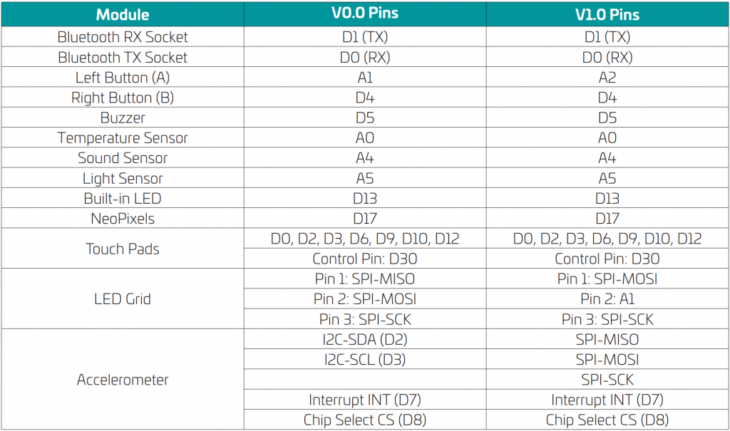
If you are using the accelerometer sensor in Maker V0.0, you should not touch or use touch pads 2 and 3 because they are sharing the same data lines (I2C). You can still use the other touch pads. Also, the sensor usually needs an offset to calibrate its values. The sensor gives raw output which is not mapped to the acceleration of gravity. The X axis points to the right while the Y axis points to the top.
Maker V1.0 has a new accelerometer where its communication lines are different from those on pin 3 and 4. The accelerometer is now using SPI pins. The sensor is also calibrated which means that you do not need to add an offset to the axis you want to read. The output of the sensor is in the unit of g (acceleration of gravity). The X axis points down while the Y axis points to the right.
Pin 3 and Pin 12 Silkscreen
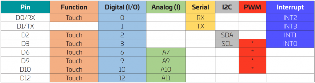
In Maker V0.0, pin 12 has an asterisk * next to it indicating that it is a pulse width modulation (PWM) pin while pin 3 does not. In Maker V1.0, this has been fixed. Pin 3 has the asterisk while pin 12 does not.
Power Regulators
The power regulators on the V1.0 board are changed to allow for a higher current value from the external power supply.
Slight Changes in Wiring
Button A is now connected to pin A2 in V1.0 while it is connected to pin A1 in V0.0. The LED Grid wiring changed as explained in the Pin Configuration Table.
Pin Configuration
The Maker board has multiple pins. Some of these pins are external (i.e. on the outer edge of the Maker) and some are internal, like the two buttons. It is important to know what each pin is connected to or capable of, to give you full control of your Maker board.
Internal Pins
External Pins